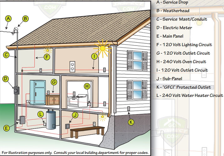
Electrical Diagram For Home
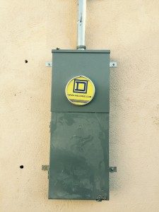
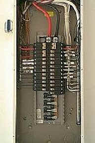
200 AMP Panel
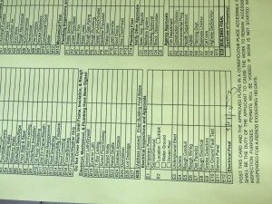
Electrical permit finalized at bottom left corner
How To Be Safe Around Incoming Power Line
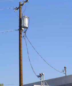
- Determine the type and number of conductors in the incoming service.
- Evaluate the height of the incoming service cables above the ground or grade level.
- Observe obstructions such as tree limbs in the area.
- Determine if the service head is correctly oriented and properly secured to the structure.
- Count the number of service conductors attached to the weather head. The number of service- entrance conductors determines the voltage of the service.
- A 120-volt, single-phase system consists of two conductors-an ungrounded phase (hot) conductor and a grounded (neutral) conductor. The 120-volt single-phase service can only supply power to single phase loads (i.e., 120-volt circuits only).
- A 120/240-volt single-phase system consists of three conductors-two ungrounded phase (hot) conductors, and one grounded (neutral) phase conductor. This system will supply both 120-volt loads and 240 single-phase loads to a dwelling.
- The size and material of the individual conductors determine the ampacity of the service conductors (ie., copper or aluminum). More than 95% of modern day services are stranded aluminum conductors.
- An underground (lateral) service extends from the transformer to the meter base of the dwelling. An underground service must be at least a #8 copper or #6 aluminum SEC. The cables must be buried a minimum of 24 inches from finished grade to the top of the cable. (Check local requirements for burial depths).
- Determine the ampacity of the service. Ampacity is determined by the smallest of three components: (1) type and size of the service-entrance cable; (2) rating of the panel; and (3) size of the main disconnect.
- Ensure that the cables are properly secured to the structure.
- Is the drip loop properly formed? Are wall and/ or roof penetrations properly sealed against water and air intrusion?
- Locate the main overcurrent protection (panel box). Examine the service cable to determine the service ampacity capability. (Note: The panel box must be located within 5 feet from the point that the SEC enters the dwelling.)
What You Should Now About Main Panel Box and Subpanels
- Remove covers and examine all enclosures for ampacity ratings.
- Determine size and material of service and feeder cables, and
compatibility with main disconnects. - Compare the wire sizes to the fuse or breaker sizes to determine if the ampacity of each breaker/fuse is correct.
- Report the presence of more than one wire connected to a breaker/fuse (double tap). NEC Article 110-14 requires that any breaker/fuse designed for more than one conductor must be clearly and permanently identified for that usage.
- Report presence of single conductor aluminum wiring in branch circuits (120-volt).
- Locate the service grounding conductor connected in the panel box.
- Trace the conductor to its point of termination (i.e., a driven rod, connected to a metal water service pipe, or a foundation-grounding conductor).
- Examine termination connections.
- The grounding conductor should be securely fastened to the building.
- A #6 copper or aluminum or larger conductor may be used if not exposed to physical damage.
- If the conductor is exposed to damage, it must be protected in a conduit. Insulated or bare aluminum or copper-clad aluminum conductors cannot be used where they will be in direct contact with masonry or earth or where subject to corrosive conditions.
- Determine type of wiring (i.e., 2-wire with armored cable (BX); 3-wire plastic coated (non-metallic, typically called Romex); knob and tube (copper wire), with cloth insulation, in a loom for protection, and installed on porcelain insulators and through tubes in joists and floors. Determine the panel box ratings. There are three types of panels used for service equipment and distribution:
- Main panels generally contain service and distribution wiring and equipment.
- Lighting and appliance panels (typically referred to as sub-panels), and Split-bus panels are typically main panels found in older homes.
- Split-bus panel boards have 1 to 6 two-pole mains in the top section with one of the mains used to supply the bottom section of the panel board.
- The bottom section of the panel board is used for the lighting and receptacle outlet loads.
- Split-bus panel boards are required to have a separate main disconnecting means ahead of them if installed after 1981.
- Each panel board is rated and tested by the manufacturer. Located either inside the panel box or on the rear side of the front cover is the manufacturer’s listing data label. This label provides the maximum voltage and ampacity ratings for the panel board. The main disconnect (breaker/fuse) cannot exceed the listed ratings. Determine panel box condition, such as missing or loose covers, interior rust, open knockouts, improperly connected boxes to the wall, or obstructions to the panel box.
Wiring
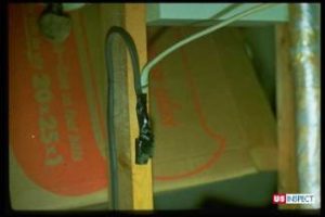
 Examine all accessible areas of the residence for unsuitable wiring, lack of sufficient receptacles, use of extension cord wiring in lieu of permanent wiring, junction boxes or outlet boxes without covers, improper or unprotected splices, defective fixtures, and any other unsafe wiring practices. Inspect all wet location areas, such as the basement, garage, and bathrooms and kitchens for proper wiring with GFCI devices. Depending on the age of the house, GFCIs may not be required.
Code-related dates:
- Exterior outlets below 6’6″ – 1973
- Bathrooms and powder rooms – 1975 and 1978
- Garages – 1978 · Kitchens – within 6′ of a sink -1987
- Unfinished basements and crawl spaces – 1990
- Wet bars – 1993
More Electrical Wiring Tips
 Check for wall switch controlled outlets in habitable rooms, bathrooms, hallways, stairwells, attached garages and outdoor entrance.
- Operate all accessible wall switches.
- Check for current in accessible receptacles in each room.
- Check polarity in each accessible receptacle, and check for ungrounded circuits.
- Look for discolored, loose or worn switch plates or receptacle covers, and any other unsafe wiring concerns or problems.
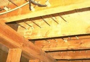
- Look for the knob and tube wiring, corroded or worn armored cable (bx) or defects in any other wiring that may exist.
- Look for missing or broken fixtures.
- There are a number of wiring types that qualify for wet locations, however, the most common type seen in residential construction is Underground Feeder (UF). This wire is acceptable for underground use, including direct burial in the earth. It should not be embedded in concrete or exposed to the sun, unless identified as sunlight-resistant.
- Check for approved weather-tight exterior boxes.
- Check that all exterior wiring is permanently marked sunlight-resistant.
- Underground Feeders are not approved for outside usage when exposed to the sunlight.
- All interior/exterior boxes, fixtures, and related electrical equipment should be properly secured.
Evaluating Electrical Wiring
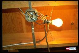
 Electric current travels through a circuit at a constant rate. Current travels at the speed of light, or 186,000 mps. (A light bulb remains at the same intensity the entire time that it is on. This indicates that the current must be the same, or the intensity of the bulb would change.) GFCIs also operate on the balance of current. If an overload occurs in a circuit, the entire wire is instantly affected (or at the speed of light). Failure will be exhibited by the most vulnerable part of the wire, which is the insulation. It does not matter whether it is cloth or plastic. (The filament in a light bulb glows red hot, but it does not burn or fail since there is no oxygen in the bulb to support combustion.) If we were to wrap the hot filament in the bulb with wiring insulation, it would immediately melt and turn to ash. This would indicate that the insulation is more vulnerable than the conductor. If the conductor is exposed it is considered unacceptable. If the wire insulation is missing it is not difficult to conclude that the wire is in poor and unsafe condition. To evaluate older wiring, follow the wiring in the basement until it goes into the walls or floor. If it changes from new to old wire, there may be concerns.